Sputtering is a kind of non-thermal vaporization which is extensively being used for producing conductive and non-conductive thin film coating on various substrates.
Introduction
Sputtering is a kind of non-thermal vaporization which is extensively being used for producing conductive and non-conductive thin film coating on various substrates. The usual illustration of its mechanism consists of a pair of adjacent opposite polarity electrodes (the anode holds the substrate to be coated and the cathode holds the target) placed in the vacuum chamber, which formation of coating over the substrate is the result of several consecutive events in the chamber including; gas ionization, ion bombardment of target surfaces, removal and throwing of the target atoms towards substrate, and then deposition on the substrate.
In the basic sputtering process, a target that attached to the cathode plate is bombarded by energetic positive ions generated in glow discharged plasma, situated in front of target. The bombardment process causes the sputtering of target atoms from its surface, which may then condense on a substrate as a thin film. Secondary electrons are also emitted from the target surface as a result of the ion bombardment. These secondary electrons play an important role in maintaining the plasma. For inception of sputtering process a plasma medium is required, and for onset of glow discharge, a minimum electrical potential is needed to be applied between the two adjacent electrodes. The glow discharge—a nearly pink-colored radiation of excited gas—occurs because the flow of high energetic electrons in their path toward anode strikes the atoms in gaseous medium. As a result, the gas atoms are stimulated, ionized and also undergo some different electron transitions, some of which are accompanied by visible light radiation.
Diode sputtering is the most common sputtering configuration in which a high electrical potential is applied between the two electrodes (substrate and target). This configuration is the simplest one, and generally used for deposition of thin conductive films for scanning electron microscopy sample preparation. The sputtering has also other configurations like triadic one, which have been developed to improve deposition rate for the sake of industrial application.
Nearly in all sputtering types, an external magnetic field is used to modify plasma and increase sputtering rate, in such cases the process is called Magnetron Sputtering. In Magnetron Sputtering, under the external magnetic field that is parallel to the cathode plate, electrons are forced to move in a spiral trajectory near the cathode rather than straight path towards the anode. Thus, the electrons generate localized plasma with higher density near the cathode. As a consequence, the plasma seems to be confined in an area near the cathode which results in the higher sputtering rate. It should be noted that, only the ions in the vicinity of cathode take part in sputtering processes, because they are under the influence of an electric field and can be accelerated towards the cathode. Hence limitation of plasma near the cathode can significantly improve sputtering rate, which consequently increases the deposition rate.
Application
The magnetron sputtering is a unique tool to produce a wide variety of conductive and non-conductive coatings on different substrates. Some of the applications are;
- Fine-grained sputter deposition for high resolution SEM & TEM.
- Conductive coating on large scale samples (wafers, compact discs, etc.).
- Metal films using Aluminum, Chromium, Cobalt, Copper, Gold, Silver, Platinum, Molybdenum, and Titanium for laboratories and industrial processes.
- Capable of co-sputtering two above-mentioned materials.
- Capable of sputtering from two different cathodes (magnetron cathodes), solely or simultaneously.
- Capable of film deposition of metal, ceramic and semiconductor.
- Capable of rotating and tilting of substrates.
- Capable of film deposition by thermal vaporization from a crucible.
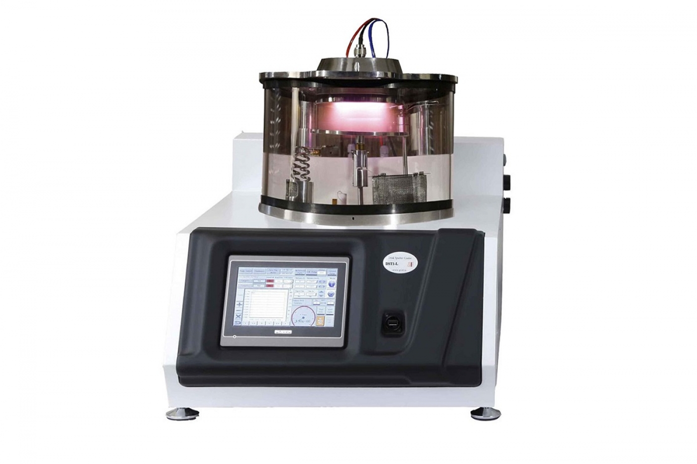
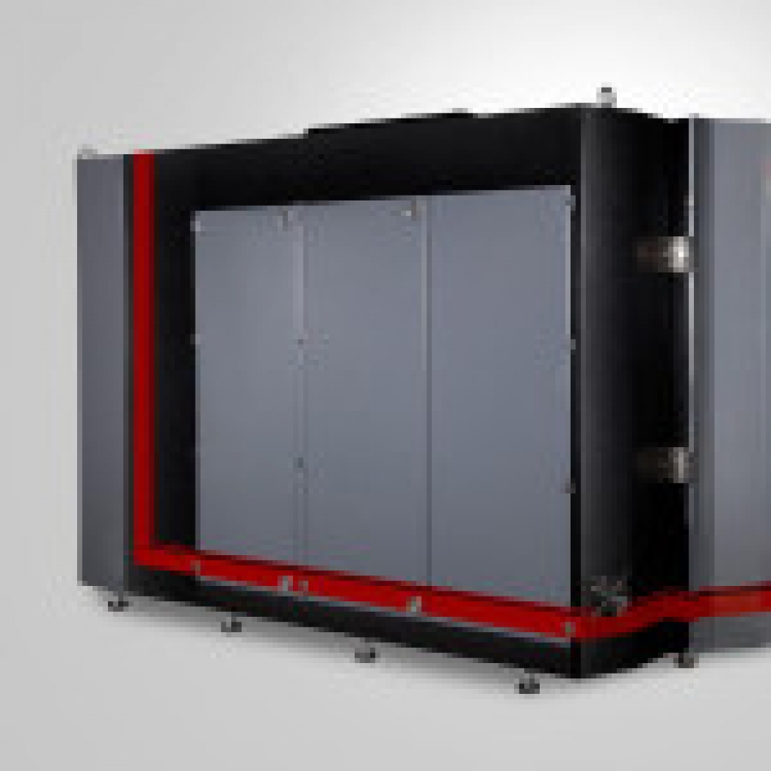
specification
The sputter coater systems provided by this company, known as Desk Sputter Coaters, are designed and produced in four different models. Details of technical specifications are presented in the following Table.
 Advantager of using nanotechnology
Magnetron Sputtering is an exquisite method for producing various coatings. In fact, each material which can undergo the sputtering conditions (plasma formation, ion bombardment, etc.) can be a good choice as a coating or substrate. Therefore, by choosing the device functional parameters appropriately, a material with different structures such as microstructures, nanostructures, nanocomposites, etc. can be produced.
Manual and maintenance
- It is important that this equipment is installed and operated by skilled personnel in accordance with these instructions. Failure to heed these instructions may result in irreversible damage.
- Ensure the main electrical power is off during any maintenance and service activities.
- In order to prevent the inner side of glass chamber coating during the sputtering process, users must cover interior wall of the glass chamber by the steel sheet that comes with the device.
- To prevent leakage, any impact and scratches should be avoided, especially in parts where vacuum chamber O-ring touches the base plate and aluminum door.
- To avoid cathode overheating and prevent degeneration of the O-rings and magnets which may result in air leakage into the vacuum chamber, the use of the cooling system is necessary. For this purpose, the best method is the use of the circulating water bath with temperature of not exceeding 20°C. If it is impossible to use the circulating water bath, you can simply use tap water instead. To do so, let the tap water enter from one of system's inlet/outlet pipe and exit from the other one. There is no difference between the inlet and outlet pipes. Note that the water flow rate should be in range of 0.3-0.5 L/min.
- The FTM can be used in two modes, Timed or Thickness. In Timed mode the coating runs for the pre-selected time and the FTM is enabled so that it can count the deposition and disabled at the end of the coating process. In Thickness mode the required deposition is selected on the FTM. When the required amount has been deposited, it automatically turns off the DC power supply.
- The system will not leak automatically, so if the pressure is not decreasing, check the last changes and start your inspection from those suspicious points.
- For more details on how to use the device, refer to the device catalog and user guide.
Safety and package
- The system operating environment must be in ambient temperature range (15 to 25 °C) in a non-condensing relative humidity of not more than 75%.
- Ensure the plugs are firmly placed in. Check that the voltage in the country and region where the appliance is intended to be used is in accordance with the device specifications.
- Due to the heavy door, please be careful about putting the door on the glass chamber and damaging of the glass.
- There is a temperature sensor on the cathode. If the circulating water is interrupted, it cause increasing of the cathode temperature and it will turn off the power supply automatically.
- The current and voltage of the plasma is adjustable by the corresponding power supply. This source provides a voltage in range of 0-800 V and current in range of 0-1.3 A. For more safety, the main power is connected when the pressure is less than 5×10⁻¹ Torr.
- Always remember that, before taking take out the sample from the chamber, the vacuum pump must be turned off (if user forgot turning off the vacuum pump, it would be automatically turned off after an hour).


 4320
4320 0
0  Printable