Before using the sensors and catalysts in a real working condition, their performance should be monitored in an isolated and fully controlled environment. Sensors and catalysts performance testing instruments can fulfill the needs of research laboratories studying on the research and development of semiconductor-based sensors as well as laboratories working on the evaluation, synthesis and development of heterogeneous catalysts.
Introduction
Before using the sensors and catalysts in a real working condition, their performance should be monitored in an isolated and fully controlled environment. Sensors and catalysts performance testing instruments can fulfill the needs of research laboratories studying on the research and development of semiconductor-based sensors as well as laboratories working on the evaluation, synthesis and development of heterogeneous catalysts.
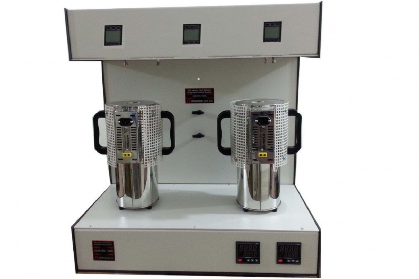
Today, sensors and catalysts are an integral part of the industries. To increase the accuracy, improve the selectivity and diminish the dimensions, the development of sensors and catalysts still continues. Therefore, development of analytical devices which specially designed for evaluation of sensors and catalysts is also of paramount importance. Continuous measurement of the electrical resistance and voltage variations is the main mechanism of these instruments. These devices are capable of probing and testing the potentiometric solid-electrolyte gas sensors (based on voltage measurement) and semiconductor gas sensors (based on electrical resistance variation). These devices are also able to check the sensor characteristics in the presence of chemical (catalytic) and physical filters.
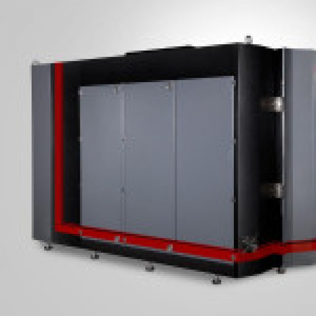
For evaluation, the sensor is firstly placed in a chamber and then the chamber is connected to the device. The cylinder containing the target gases is connected to the device gas inlets through the steel pipes, while the device gas outlet is connected to the ventilation system. Afterwards, gas mixture with a certain flow, pressure and concentration is passed into the chamber. As soon as the contact between sensor and gas occurs, some signals (in the form of voltage or electrical resistance variation) will be received. By stabilizing the signal and completing the sensor response, the target gas flow is cut off. Finally, by plotting the diagram of signal vs. time or gas concentration, the sensor behavior can be evaluated.
Application
Some applications of this device are as follows:
- Measurement of the heterogeneous catalysts performance
- Performance of semiconductor sensors in terms of sensitivity and selectivity
specification
The GSCITS is designed and constructed by combining two devices, i.e. catalyst (to measure the heterogeneous catalysts performance) and semiconductor sensors testing system (for sensitivity and selectivity). Details of technical specifications are presented in the following Table.
 Advantager of using nanotechnology
One of the achievements of nanotechnology is fabrication and optimization of semiconductor sensors. Development of many catalysts is also dependent on nanotechnology. Therefore, GSCITS can play a significant role in the field of nanotechnology. In other words, this device is able to evaluate the sensors and catalytic activities of nanomaterials.
Manual and maintenance
- The gas flow is regulated by Mass Flow Controllers (MFCs) and using the software. MFCs can be controlled manually.
- Device operating range for measuring the electrical resistance is 5×10² to 5×10¹⁰ Ω.
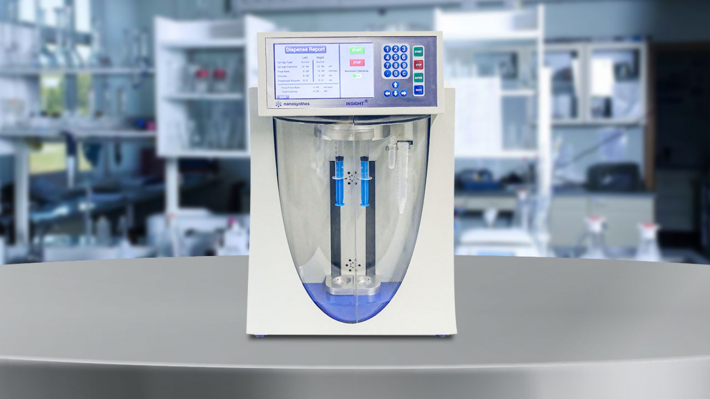
- Moisturize the gas by using a syringe pump with an accuracy of 1 μL/h. The required amount of moisture is calculated by the software and given to the user.
- For more details on how to use the device, refer to the device catalog and user guide.
Safety and package
- Power outlet should have earth connection and three inputs for device electric power.
- Use a working table with length, width and height of at least 1.7, 0.7 and 9.0 m, respectively.
- Providing cylinders containing different gases with corresponding regulators is essential.
- The regulators must have outlet with external diameter of 0.125 inch.
- To increase the device lifespan, the input gas pressure must be less than 4 bar.
- The temperature and relative humidity of the device installation place should not exceed 50 °C and 80%, respectively.
- The presence of outlet for discharging the device exhaust gases is essential.


 3020
3020 0
0  Printable